
Why Traditional Blower Aerodynamics Fail at 100,000 RPM: A Fluid Dynamic Inquiry into Maglev Centrif
Post time: 2026-08-25 15:14:20
When industrial engineers evaluate aeration equipment for municipal wastewater treatment or pneumatic conveying, standard multi-stage centrifugal or positive displacement blowers are often the baseline. However, as plant optimization targets shift toward minimizing total lifecycle energy consumption, high-speed direct-drive magnetic levitation (maglev) turbo blowers have emerged as the definitive upgrade.
Yet, transitioning an industrial blower to operate at rotational speeds scaling up to 100,000 RPM fundamentally alters fluid behavior inside the machine. At these velocities, traditional blade design rules of thumb collapse. To understand how contemporary engineering overcomes these aerodynamic roadblocks, we must examine the specific physical bottlenecks encountered inside the compression stage and how modern design methodologies resolve them.
What Happens When Impeller Tip Speeds Approach Mach 1?
The primary performance driver in a centrifugal compressor is the peripheral velocity of the impeller eye and tip. When rotational velocity reaches extreme tiers, the relative velocity of air entering and leaving the blade channels approaches or exceeds local sonic speeds.
Compressibility Shockwaves: At tip speeds exceeding 300 to 400 meters per second, localized shockwaves form along the suction surface of the impeller blades. These miniature shock fronts cause abrupt boundary layer separation, triggering sudden aerodynamic stalls and localized flow reversal.
Centrifugal Stress vs. Aerodynamic Load: The structural integrity of the impeller material itself becomes tightly coupled with aerodynamic efficiency. Traditional cast aluminum alloys struggle with the immense centrifugal forces at 100,000 RPM, necessitating high-strength titanium or forged aerospace-grade aluminum implementations that maintain precise blade geometry under high thermal and mechanical stress.
Incidence Angle Sensitivity: At ultra-high RPMs, even micro-variations in incoming mass flow alter the incidence angle of air hitting the leading edge. Designing an impeller that maintains smooth flow attachment across a wide turndown ratio requires complex backward-curved blade stacking rather than radial exit blades.
How Can We Widen the Surge Margin Without Sacrificing Efficiency?
Every centrifugal compressor operates within a constrained performance envelope bounded by the "surge line" on the left and the "choke line" on the right. Operating too close to the surge line during low-demand cycles can induce severe flow instability, pressure oscillations, and mechanical damage.
The Danger of Deep Surge: When backpressure from the process system exceeds the pressure generation capability of the impeller at reduced mass flow, flow reverses violently inside the volute. This cyclic oscillation stresses both the impeller and the magnetic bearing control loops.
Variable Inlet Guide Vanes (IGV): Rather than relying solely on throttle valves—which waste energy by creating artificial pressure drops—advanced maglev blowers integrate variable inlet guide vanes or variable diffuser geometry. By pre-swirling the incoming air in the direction of impeller rotation, the effective operating envelope shifts cleanly to the left, expanding the stable turndown range.
Aero-Thermal Feedback Loops: Modern control integration monitors real-time discharge temperature and pressure gradients, allowing the inverter to dynamically adjust rotational speed preemptively before flow instability reaches the critical surge threshold.
Why Are 3D-Contoured Flow Channels Essential for Modern Volutes?
Once air exits the spinning impeller at extreme kinetic energy, that velocity must be converted into static pressure efficiently within the stationary casing, or volute. A poorly matched volute results in severe secondary flow losses and turbulent dissipation.
Eliminating Secondary Vortex Generation: Fluid inside a high-speed scroll does not travel in neat, parallel sheets. Secondary flows and horseshoe vortices naturally form along the hub and shroud walls due to cross-channel pressure gradients.
Fully Spatial Blade and Volute Profiling: Utilizing multi-axis computational fluid dynamics (CFD) optimization, modern engineering replaces conventional two-dimensional stamping with true 3D-sculpted impellers and matching asymmetric volutes. Each meridian curve is tailored to manage the local momentum thickness of the boundary layer.
Skin Friction Reduction: Surface finish micro-tolerances inside the volute and diffuser passages are critical. By applying specialized flow-conditioning finishes to the cast or machined scroll surfaces, parasitic skin friction losses are minimized, directly preserving the mechanical energy transferred from the magnetic motor drive.
Frequently Asked Questions on High-Speed Maglev Aerodynamics
1. How does magnetic levitation support extreme impeller designs?
Unlike oil-lubricated systems that suffer from shaft whip and thermal expansion limits at high speeds, active magnetic bearings maintain zero physical contact and provide rigid spatial positioning. This allows the rotor-impeller assembly to spin with absolute concentric stability, preventing blade-to-shroud rub even when operating near critical aerodynamic thresholds.
2. Does higher rotational speed always equate to higher efficiency?
Not automatically. While higher tip speeds yield higher pressure ratios per stage, they also exponentially increase aerodynamic losses if the flow channels are not meticulously contoured. True high efficiency is achieved only when aerodynamic profiling matches the exact operating map of the target industrial application.
3. How do ambient temperature and humidity shifts affect ultra-high-speed impellers?
Changes in air density directly alter the mass flow and volumetric ratio entering the compressor. Advanced maglev control systems compensate for seasonal climatic variations by monitoring inlet conditions and automatically modulating motor frequency to maintain constant mass flow output for biological aeration tanks.
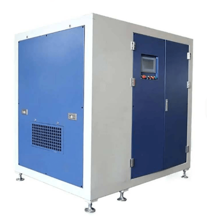
Maglev Turbo Blowers Product Information
Web: http://www.greentechblower.com (Group Web) ‖ http://www.zqblower.cn (Chinese) ‖ http://www.ringblower.cn/ (Ring blower) ‖ http://www.china-blower.com (Roots Blower) ‖ https://www.zibovacuumpump.com (Vacuum Pump)